- 您现在的位置:买卖IC网 > Sheet目录1012 > TX2SS-LT-3V-TH (Panasonic Electric Works)RELAY GENERAL PURPOSE DPDT 2A 3V
�� ��
��
��TX-TH�
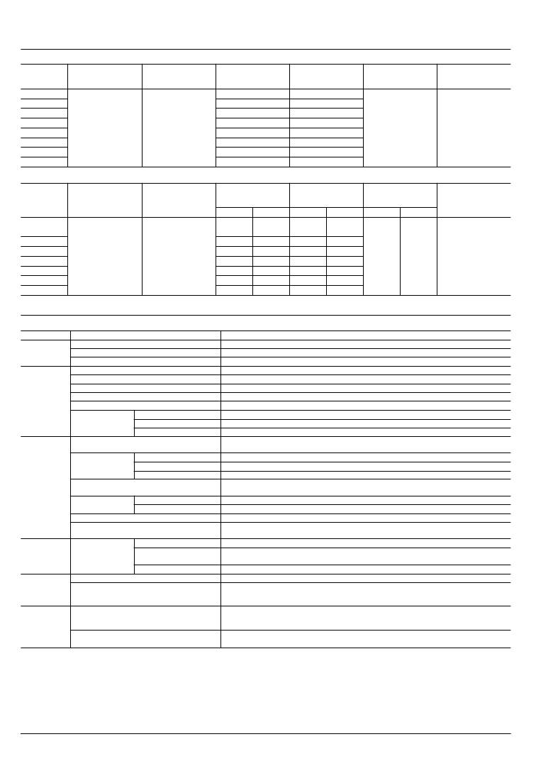
�2)� 1� coil� latching�
�Nominal� coil�
�voltage�
�Set� voltage�
�(at� 20� °� C� 68� °� F� )�
�Reset� voltage�
�(at� 20� °� C� 68� °� F� )�
�Nominal� operating�
�current�
�[� ±� 10%]� (at� 20� °� C� 68� °� F� )�
�Coil� resistance�
�[� ±� 10%]� (at� 20� °� C� 68� °� F� )�
�Nominal� operating�
�power�
�Max.� applied� voltage�
�(at� 20� °� C� 68� °� F� )�
�1.5V� DC�
�3V� DC�
�4.5V� DC�
�66.7mA�
�33.3mA�
�22.2mA�
�22.5� ?�
�90� ?�
�202.5� ?�
�5V� DC�
�6V� DC�
�9V� DC�
�75%V� or� less� of�
�nominal� voltage*�
�(Initial)�
�75%V� or� less� of�
�nominal� voltage*�
�(Initial)�
�20mA�
�16.7mA�
�11.1mA�
�250� ?�
�360� ?�
�810� ?�
�100mW�
�150%V� of�
�nominal� voltage�
�12V� DC�
�24V� DC�
�3)� 2� coil� latching� (L2,� LT)�
�8.3mA�
�4.2mA�
�1,440� ?�
�5,760� ?�
�Nominal� coil�
�voltage�
�Set� voltage�
�(at� 20� °� C� 68� °� F� )�
�Reset� voltage�
�(at� 20� °� C� 68� °� F� )�
�Nominal� operating�
�current�
�[� ±� 10%]� (at� 20� °� C� 6� 8� °� F� )�
�Set� coil� Reset� coil�
�Coil� resistance�
�[� ±� 10%]� (at� 20� °� C� 68� °� F� )�
�Set� coil�
�Reset� coil�
�Nominal� operating�
�power�
�Set� coil�
�Reset� coil�
�Max.� applied� voltage�
�(at� 20� °� C� 68� °� F�
�1.5V� DC�
�93.8mA� 93.8mA�
�16� ?�
�16� ?�
�3V� DC�
�4.5V� DC�
�46.7mA�
�31mA�
�46.7mA�
�31mA�
�64.3� ?�
�145� ?�
�64.3� ?�
�145� ?�
�5V� DC�
�6V� DC�
�9V� DC�
�75%V� or� less� of�
�nominal� voltage*�
�(Initial)�
�75%V� or� less� of�
�nominal� voltage*�
�(Initial)�
�28.1mA�
�23.3mA�
�15.5mA�
�28.1mA�
�23.3mA�
�15.5mA�
�178� ?�
�257� ?�
�579� ?�
�178� ?�
�257� ?�
�579� ?�
�140mW�
�140mW�
�150%V� of�
�nominal� voltage�
�12V� DC�
�24V� DC�
�11.7mA�
�5.8mA�
�11.7mA�
�5.8mA�
�1,028� ?�
�4,114� ?�
�1,028� ?�
�4,114� ?�
�*Pulse� drive� (JIS� C� 5442-1986)�
�2.� Speci?cations�
�Characteristics�
�Contact�
�Rating�
�Item�
�Arrangement�
�Initial� contact� resistance,� max.�
�Contact� material�
�Nominal� switching� capacity�
�Max.� switching� power�
�Max.� switching� voltage�
�Max.� switching� current�
�Min.� switching� capacity� (Reference� value)*� 1�
�Speci?cations�
�2� Form� C�
�Max.� 100� m� ?� (By� voltage� drop� 6� V� DC� 1A)�
�Ag+Au� plating�
�2� A� 30� V� DC,� 0.5� A� 125� V� AC� (resistive� load)�
�60� W,� 60� VA� (resistive� load)�
�220V� DC,� 250V� AC�
�7.5� A� (When� used� at� 7.5� A.� Regarding� connection� method,� you� must� follow� the� precaution,� below*.)�
�10� μ� A� 10mV� DC�
�Nominal� operating�
�power�
�Single� side� stable�
�1� coil� latching�
�2� coil� latching�
�140� mW� (1.5� to� 24� V� DC),� 270� mW� (48� V� DC)�
�100� mW� (1.5� to� 24� V� DC)�
�140� mW� (1.5� to� 24� V� DC)�
�Insulation� resistance� (Initial)�
�Min.� 1,000M� ?� (at� 500V� DC)�
�Measurement� at� same� location� as� “Initial� breakdown� voltage”� section.�
�Breakdown� voltage�
�(Initial)�
�Between� open� contacts�
�Between� contact� and� coil�
�Between� contact� sets�
�1,000� Vrms� for� 1min.� (Detection� current:� 10mA)�
�2,000� Vrms� for� 1min.� (Detection� current:� 10mA)�
�1,000� Vrms� for� 1min.� (Detection� current:� 10mA)�
�Electrical�
�characteristics�
�Temperature� rise� (at� 20� °� C� 68� °� F� )�
�Max.� 50� °� C�
�(By� resistive� method,� nominal� coil� voltage� applied� to� the� coil;� contact� carrying� current:� 2A.)�
�Surge� breakdown�
�voltage� (Initial)�
�Between� open� contacts�
�Between� contacts� and� coil�
�1,500� V� (10� ×� 160� μ� s)� (FCC� Part� 68)�
�2,500� V� (2� ×� 10� μ� s)� (Telcordia)�
�Operate� time� [Set� time]� (at� 20� °� C� 68� °� F� )�
�Release� time� [Reset� time]� (at� 20� °� C� 68� °� F� )�
�Max.� 4� ms� [Max.� 4� ms]� (Nominal� coil� voltage� applied� to� the� coil,� excluding� contact� bounce� time.)�
�Max.� 4� ms� [Max.� 4� ms]� (Nominal� coil� voltage� applied� to� the� coil,� excluding� contact� bounce� time.)�
�(without� diode)�
�Mechanical�
�characteristics�
�Shock� resistance�
�Vibration� resistance�
�Mechanical�
�Functional�
�Destructive�
�Functional�
�Destructive�
�Min.� 750� m/s� 2� (Half-wave� pulse� of� sine� wave:� 6� ms;� detection� time:� 10� μ� s.)�
�Min.� 1,000� m/s� 2� (Half-wave� pulse� of� sine� wave:� 6� ms.)�
�10� to� 55� Hz� at� double� amplitude� of� 3.3� mm� (Detection� time:� 10� μ� s.)�
�10� to� 55� Hz� at� double� amplitude� of� 5� mm�
�Min.� 10� 8� (at� 180� cpm)�
�Expected� life�
�Conditions�
�Electrical�
�Conditions� for� operation,� transport� and� storage*� 2�
�Min.� 10� 5� (2� A� 30� V� DC� resistive),� 5� � 10� 5� (1� A� 30� V� DC� resistive),�
�Min.� 10� 5� (0.5� A� 125� V� AC� resistive)� (at� 20� cpm)�
�Min.� 2� ×� 10� 5� (7.5� A� inrush� (250� ms)/1.5� A� normal� 30� V� AC� (cos� φ� =� 0.4))� (ON/OFF� =� 1s/9s)�
�Ambient� temperature:� –40� °� C� to� +85� °� C� (up� to� 24� V� coil)� –40� °� F� to� +185� °� F�
�[–40� °� C� to� +70� °� C� (48� V� coil)� –40� °� F� to� +158� °� F� ];�
�Humidity:� 5� to� 85%� R.H.� (Not� freezing� and� condensing� at� low� temperature)�
�Unit� weight�
�Max.� operating� speed� (at� rated� load)�
�20� cpm�
�Approx.� 2� g� .071� oz�
�Notes:� *1� This� value� can� change� due� to� the� switching� frequency,� environmental� conditions,� and� desired� reliability� level,� therefore� it� is� recommended� to� check� this� with� the�
�actual� load.�
�*2� Refer� to� 6.� Conditions� for� operation,� transport� and� storage� mentioned� in� AMBIENT� ENVIRONMENT� (Page� 24).�
�Panasonic� Corporation�
�Automation� Controls� Business� Unit�
�industrial.panasonic.com/ac/e�
�ASCTB20E� 201201-T�
�发布紧急采购,3分钟左右您将得到回复。
相关PDF资料
TXD2SL-L-5V-Z
RELAY GENERAL PURPOSE DPDT 2A 5V
TXS2SL-L2-4.5V
RELAY GEN PURPOSE DPDT 1A 4.5V
U206-006-R
ADAPTER USB - IEEE PARALLEL 6'
U209-000-R
ADAPTER USB TO SERIAL 17"
VE13M00300K--
压敏电阻 30volts 13mm 10%
UC232R-10
CABLE USB RS232 EMBEDDED 10CM
UEZGUI-1788-43WQS
KIT DEV 4.3" TOUCH SCREEN
UEZGUI-1788-70WVE
KIT DEV 7" TOUCH SCREEN
相关代理商/技术参数
TX2SS-LT-4.5V
功能描述:低信号继电器 - PCB TX2SS-LT-12V - TX Relay (Alternate footp
RoHS:否 制造商:NEC 触点形式:2 Form C (DPDT-BM) 触点电流额定值: 线圈电压:5 V 最大开关电流:1 A 线圈电流:1 A 线圈类型:Non-Latching 功耗:140 mW 端接类型:SMT 绝缘: 介入损耗:
TX2SS-LT-4.5V-TH
功能描述:低信号继电器 - PCB RELAY DPDT 7.5A INRUSH 4.5VDC
RoHS:否 制造商:NEC 触点形式:2 Form C (DPDT-BM) 触点电流额定值: 线圈电压:5 V 最大开关电流:1 A 线圈电流:1 A 线圈类型:Non-Latching 功耗:140 mW 端接类型:SMT 绝缘: 介入损耗:
TX2SS-LT-4.5V-X
功能描述:低信号继电器 - PCB TX Relay (Alternate footprint SMD SS typ
RoHS:否 制造商:NEC 触点形式:2 Form C (DPDT-BM) 触点电流额定值: 线圈电压:5 V 最大开关电流:1 A 线圈电流:1 A 线圈类型:Non-Latching 功耗:140 mW 端接类型:SMT 绝缘: 介入损耗:
TX2SSLT4.5VZ
制造商:Panasonic 功能描述:Electromechanical Relay DPDT 2A 4.5VDC 101.2Ohm Surface Mount
TX2SS-LT-4.5V-Z
功能描述:低信号继电器 - PCB TX Relay (Alternate footprint SMD SS typ
RoHS:否 制造商:NEC 触点形式:2 Form C (DPDT-BM) 触点电流额定值: 线圈电压:5 V 最大开关电流:1 A 线圈电流:1 A 线圈类型:Non-Latching 功耗:140 mW 端接类型:SMT 绝缘: 介入损耗:
TX2SS-LT-5V
制造商:Panasonic Electric Works 功能描述:
TX2SS-LT-6V
制造商:PANASONIC 制造商全称:Panasonic Semiconductor 功能描述:Best seller with broad lineup and AC 2000 V breakdown voltage.
TX2SS-LT-9V
功能描述:低信号继电器 - PCB TX2SS-LT-9V - TX Relay (Alternate footpr
RoHS:否 制造商:NEC 触点形式:2 Form C (DPDT-BM) 触点电流额定值: 线圈电压:5 V 最大开关电流:1 A 线圈电流:1 A 线圈类型:Non-Latching 功耗:140 mW 端接类型:SMT 绝缘: 介入损耗: